Well design
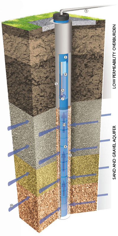
Discharge Pipe From Boode Wellhead
-
Concrete Slab For The Well House Foundations
(Note: Many Details At The Top Of The Borehole Are Not Shown, In Order To Keep The Diagram Simple.
For Example:- The Well House, Control Valve, Flow Meter, Electricity Supply Cable Etc.) -
Boode PVC Pump Chamber Casing
-
Pumping Water Level In The Borehole
-
Cement Or Bentonite Grout Sealing The Annulus Around The Pump Chamber Casing
-
Electric Submersible Pump
-
Water Inflow To The Pump Intake
-
Boode PVC Well Screen
-
Gravel Filter Pack Filling The Annulus Around The Well Screen
-
Groundwater Is Drawn Through The Screen Slots And Flows Up To The Pump Intake
-
Groundwater Flows Through The Sand And Gravel Aquifer To The Well Screen
Selection & precaution of pvc casing and screen
An informed guide to the Selection of, and Precautions to be taken, in relation to the correct installation of Boode PVC Casing and Screen Systems. ![]()
Boode B.V. would like to acknowledge the contribution of the text and drawings by David M. Ball, Hydrogeologist, Dublin.